

The 8-bit microcontroller platform supports four product series:
REQUIRED COMPONENTS :
- The STM8S103F Development Board
- The ST link V2 programmer
- A breadboard
- Jumper wires
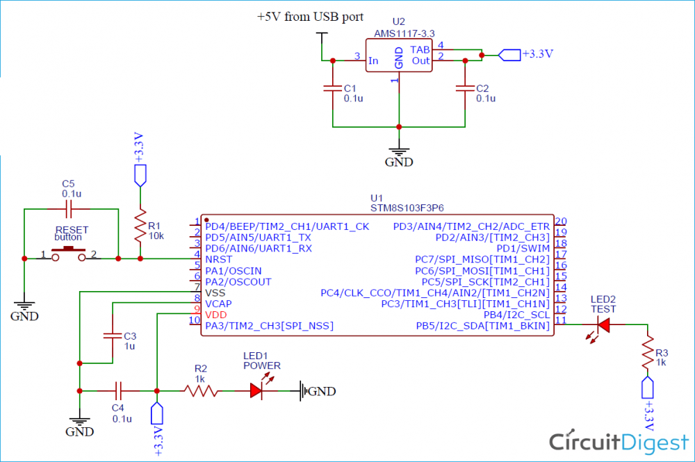
Since we will implement the blink example using the LED onboard the STM8S103F, there is not much to do in terms of schematics. However, for those who may not be familiar with the process of connecting the ST link programmer to the STM8S103F board, the connection is described in the schematics below:

Setting up the Arduino IDE
Step 2: Follow File -> Preferences to open the preferences window and paste the link given below into the additional boards manage URL text box and click on OK.


Now the Arduino IDE is ready for programming the STM8S103F3 Development Board. Let us set up the board, connect it to the computer, and program for a simple LED blink.
Arduino Pin Mapping for STM8S103F3
If you want to proceed from here, you need to know how to address each pin on the STM8S103F3 Development board. The pin mapping can be understood from this image below-
For example from the STM8S103F3 Board circuit diagram, we know that the on-board LED is connected to PB5. To address this pin on Arduino, we have to use 3, hence the program can be written as-

CODE
As mentioned during the introduction, for demonstration purposes, we will upload the blink example to the STM8S103F Development Board. You can use the generic blink example (File -> Example -> Basics -> Blink) or use the blink example among the STM8s Specific libraries (File -> Example -> Generic_Example -> Basics -> Blink).
void setup() {
  // initialize digital pin LED_BUILTIN as an output.
  pinMode(LED_BUILTIN, OUTPUT);
}
// the loop function runs over and over again forever
void loop() {
  digitalWrite(LED_BUILTIN, HIGH);   // turn the LED on (HIGH is the voltage level)
  delay(1000);                       // wait for a second
  digitalWrite(LED_BUILTIN, LOW);    // turn the LED off by making the voltage LOW
  delay(1000);                       // wait for a second
}
I believe the code for the blink example needs no explanation.

